Power and wiring
Bus Wire Gauge Calculator
Quick answer
A 25 foot DCC bus at 5 amps needs 14 AWG wire to keep the drop under half a volt. Remember the current goes out and back, so a 25 foot bus is 50 feet of copper. Plan a feeder drop about every three feet, so roughly 9 on that run.
The DCC bus is the pair of wires running under the layout carrying power and signal from the command station to the track. Getting it wrong produces symptoms that mimic everything else: locomotives slowing at the far end, sound cutting out, shorts the booster fails to detect, decoders resetting for no visible reason.
The calculation is ordinary electrical engineering. Voltage drop is current times resistance, and resistance is the wire's ohms per foot times the length. The part people miss is that the current travels out on one conductor and back on the other, so a 25 foot bus is 50 feet of copper in the circuit. Calculating with the one way distance halves your answer, and it is the most common wiring mistake on a large layout.
The working limit used here is half a volt. Past that the booster starts to have trouble distinguishing a heavy load from a short circuit, which is the failure that matters more than the lost voltage itself.
Bus wire gauge calculator
Minimum bus gauge
Wire and connections for this bus
Top matches update when you change your numbers.
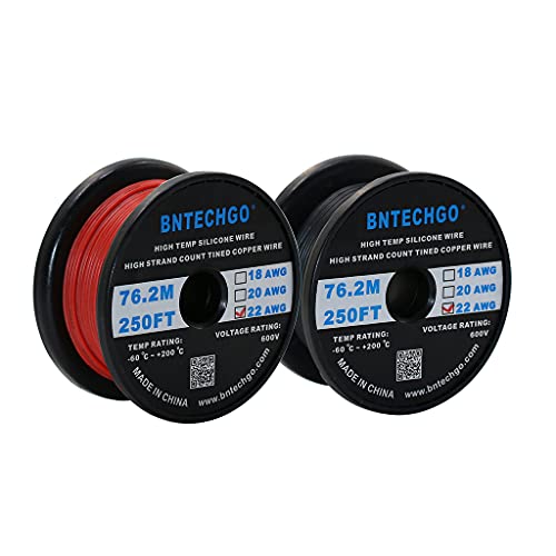
BNTECHGO 22 AWG Silicone Wire Red and Black 250 ft Stranded Tinned Copper
$46.98Feeder wire in the two colours you need, tinned and silicone jacketed so it stays flexible and takes solder easily. Red and black on a spool each removes a whole class of wiring mistake.
Best for: track feeders
Check price on Amazon
BNTECHGO 22 Gauge Silicone Wire Spool 250 ft Brown Stranded Tinned Copper
$25.98A third colour, which is what you want for accessory and turnout wiring so it is never confused with the track bus.
Best for: accessory and turnout wiring
Check price on Amazon
Terminal Block 8 Circuits 600V 15A Dual Row Screw Terminal Strip 6 Sets
$13.89Screw terminals let a section of the layout be disconnected for fault finding without cutting anything. Tracing a short on a layout wired entirely with solder joints is genuinely miserable.
Best for: making layout wiring diagnosable
Check price on Amazon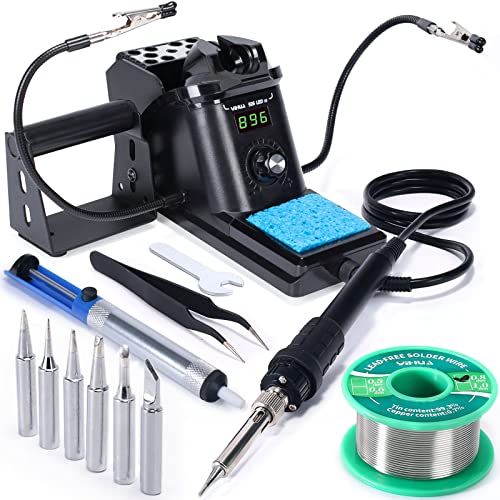
YIHUA 926 III 60W Digital Soldering Iron Station Kit with Helping Hands
$39.99A temperature controlled station rather than a plain iron. Soldering a feeder to rail needs heat delivered fast, and a cheap uncontrolled iron melts the ties while failing to make the joint.
Best for: soldering rail feeders without melting ties
Check price on Amazon
Xuron 410 Micro-Shear Flush Cutters
$16.04A smaller cutter for wire, decoder leads and plastic sprue, where the full size rail cutter is clumsy.
Best for: wire and fine detail work
Check price on Amazon
Digitrax 8 Amp Auto-Reversing DCC Booster
$212.99Eight amps with auto-reversing built in, which is what a reversing loop needs to avoid a short every time a train crosses the gap. It is a booster only and needs a command station.
Best for: adding current and a reversing loop to a Digitrax layout
Check price on AmazonWhat gauge does your bus need?
The lightest gauge that keeps the drop under half a volt, at three common booster currents, with the feeder count for a drop every three feet.
A 25 foot bus needs 16 AWG at 3 amps, 14 AWG at 5 amps and 12 AWG at 8 amps, so the booster size changes the wire as much as the length does.
| Bus length | At 3 A | At 5 A | At 8 A | Feeder drops |
|---|---|---|---|---|
| 10 ft | 18 AWG | 16 AWG | 14 AWG | 4 |
| 15 ft | 16 AWG | 14 AWG | 12 AWG | 5 |
| 20 ft | 16 AWG | 12 AWG | 10 AWG | 7 |
| 25 ft | 14 AWG | 12 AWG | 10 AWG | 9 |
| 30 ft | 14 AWG | 12 AWG | 10 AWG | 10 |
| 40 ft | 12 AWG | 10 AWG | 10 AWG | 14 |
| 50 ft | 12 AWG | 10 AWG | 10 AWG | 17 |
| 60 ft | 10 AWG | 10 AWG | 10 AWG | 20 |
The cheapest way to reduce the gauge required is to shorten the bus by splitting the layout into power districts, rather than running one long bus from a single point.
What each gauge actually costs you
Round trip resistance and the resulting drop at 5 amps over two common bus lengths.
At 5 amps over 25 feet, 18 AWG drops 1.6 volts and 14 AWG drops 0.63 volts, which is the difference between a layout that misbehaves at the far end and one that does not.
| Gauge | Ohms per 1,000 ft | Drop at 25 ft | Drop at 50 ft | OK at 25 ft? |
|---|---|---|---|---|
| 10 AWG | 0.9989 ohms | 0.25 V | 0.499 V | Yes |
| 12 AWG | 1.588 ohms | 0.397 V | 0.794 V | Yes |
| 14 AWG | 2.525 ohms | 0.631 V | 1.263 V | No |
| 16 AWG | 4.016 ohms | 1.004 V | 2.008 V | No |
| 18 AWG | 6.385 ohms | 1.596 V | 3.193 V | No |
Resistance figures are standard copper wire table values. Stranded wire is easier to work with under a layout and takes solder more readily than solid.
Feeders, and why rail joiners are not wiring
The bus does not power the track. Feeders do, and they are short wires soldered from the bus up to the rail.
This matters because a rail joiner is a mechanical connection, not an electrical one. It works when new and clean, and it degrades as the joint oxidises and as the track expands and contracts with humidity. A layout relying on joiners for continuity develops dead sections over a year or two, and they move around, which makes them genuinely maddening to find.
The standard practice is a feeder to every piece of rail. The common compromise is a feeder every three feet. Feeders are short, so they can be far thinner than the bus: 22 AWG is normal, and over a few inches the drop is negligible.
Twisting the bus, and what it is actually for
The usual advice is to twist the two bus wires a few turns per foot. It is worth doing, and the reason is not voltage drop at all.
A DCC bus carries a square wave at a few kilohertz, and a pair of parallel wires running tens of feet is an antenna. Twisting them means each twist radiates opposite to the last, so the emissions largely cancel. It also reduces the loop area, lowering the inductance of the run and keeping the waveform edges clean at the far end, which is part of why decoders read reliably there.
On a short bus none of this matters much. On a long one it is free insurance. The related question is termination: on runs past roughly thirty feet, a resistor and capacitor in series across the far end damps the reflection that rings off an unterminated cable. Unnecessary on a small layout, worth adding on a big one.
Frequently asked questions
What gauge wire should I use for a DCC bus?
For most home layouts, 14 AWG covers a bus up to about 30 feet at 5 amps. Short buses under 15 feet can use 16 AWG, and long runs or 8 amp boosters want 12 AWG. Going heavier than needed costs little and does no harm; going lighter causes faults that only appear at the far end under load.
Why is the round trip distance twice the bus length?
Because the circuit is a loop. Current flows out along one conductor and returns along the other, so both lengths contribute resistance. A 25 foot bus is 50 feet of copper. Calculating with the one way distance halves the apparent voltage drop, and it is the single most common wiring mistake on a large layout.
How often should I add feeder drops?
Every three feet is the common practical rule, and a feeder to every individual piece of rail is the counsel of perfection. Rail joiners are a mechanical connection rather than a reliable electrical one, so a layout that depends on them for continuity develops dead sections as it ages, and those sections move around.
What gauge should feeders be?
Around 22 AWG is normal and entirely adequate. Feeders are only a few inches long, so the resistance over that distance is negligible even in thin wire. Thin feeders are also much easier to solder to the side of the rail without melting the ties, and far easier to hide once the track is ballasted.
Should I twist the DCC bus wires?
Yes, a few turns per foot. It cancels radiated emissions, because successive twists radiate in opposite senses, and it lowers the loop inductance which keeps the DCC waveform edges clean at the far end. It costs nothing and removes a variable. On a short bus it makes little difference; on a long one it is worth doing.
Can I use solid or stranded wire?
Either works electrically at the same gauge. Stranded is easier to work with under a layout because it flexes rather than fatiguing at a bend, and it takes solder readily. Solid wire holds its shape, which some people prefer for a tidy run. Tinned stranded wire is the usual choice for both bus and feeders.
Researched, not professional advice. This page is compiled from published manufacturer specifications, instruction manuals, published NMRA standards and recommended practices, and owner-review consensus, not hands-on testing. Figures described as a rule of thumb are hobby convention rather than a standard, and they are labelled that way wherever they appear. Always check a radius, a clearance or a grade against your own equipment before you cut wood or lay rail, because manufacturers vary and so does what your specific models will tolerate. Any permanent mains wiring in a layout room is work for a licensed electrician to your local code.